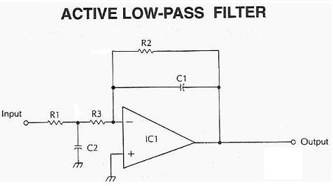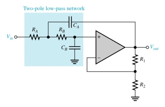

We don’t need two identical solution sets we need only one solution that is common to both equations. Unfortunately, this over-constrains the problem and limits the search for the best results. This would result in two pairs of identical solutions. One approach that might tempt us would be to first normalize the equations so that the coefficient of the R2 2 terms in each was set to 1, and to then equate the coefficients of the R2 0 and R2 1 terms. But the six parameters other than R2 in these equations provide an overabundance of options for meeting that requirement. The filter design requires that at least one solution to be equal to at least one solution to. We can think of the result as two second order equations in R2: One way to start to determine sets of component values which satisfy these equations is to solve for R1 and substitute that expression into and. Regardless of the nature of p1 and p2, we can always write H(s) as The real portions of all poles are negative, and if p1 and p2 are complex, their imaginary portions are negatives of one another. p1 and p2 can be real and identical, real and different, or complex. One must be real, and without loss of generality, that will be p3. The transfer function of this circuit is given byĪ third order filter has three poles: p1, p2 and p3. In analyzing this filter, I’ll take a slightly different path from the one pursued in the original article. Figure 1 Third order single op amp Sallen Key low-pass filter The effect of the op amp’s rising output impedance can is accordingly rendered negligible.įigure 1 shows a third order low pass Sallen-Key filter implemented with a single op amp. By attenuating the portion of input signal which reaches the filter capacitor connected to the output, stopband rejection is significantly improved. A third order design remedies this by inserting an R-C section (whose capacitor is grounded) between the input and output. The result is that higher frequency stopband rejection is a lot worse than intended. The section’s input signal is capacitively coupled to the op amp output. Well, why not? If you can add an extra pole’s worth of attenuation without having to add an op amp, why wouldn’t you at least consider this? But there’s an even better reason – avoiding stopband leakage (see the section of the same name in the article cited above.) Briefly, as op amp open loop gain falls with higher frequencies in a second order Sallen Key section, its output impedance rises. Why all this effort for third order filters? Given filter poles and capacitor and resistor E-series values and range limits, the program tests all possible component combinations and identifies the solutions with the lowest (and what the heck, the highest) aggregate component value sensitivities.

This article discusses an approach and provides an executable program that remedies this situation. This is tedious, and there is no guarantee that the lowest sensitivity solution will ever be found. One limitation of this procedure is that it relies on the user to specify different combinations of component values in search of solutions with ever lower sensitivities.


 0 kommentar(er)
